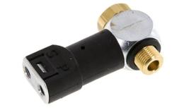
Materials:
Brass, nickel-plated brass, plastic, gaskets: NBR
Switching time:
3 ms
Electrical connection loads:
Max. 2 A, 0 - 48 V DC, 250 V AC
Power consumption:
DC: 5 W, AC 10 VA
Protection class:
IP 40
Operation:
A signal coupling takes over the function of a limit switch (pneumatic or electrical signal). The screw is screwed into the inlet hole of a cylinder and scans the working pressure of the cylinder. When there is no more pressure on the clutch, the clutch switches from (P) 1 to (S) 5.
Please note:
Signal couplings detect the reaching of the end position only by a loss of pressure. However, this pressure loss can also occur if the cylinder in its control range is blocked. If there is a risk of such a blockage, we recommend the use of pneumatic cylinder switches that react directly to the magnetic field of a magnetic piston.
Advantages:
• Purely pneumatic control device, no electrical energy required,
• Easy installation,
• Compact shape
All statements are intended as non-binding guidelines! We are not liable for data selection not confirmed in writing. Pressure data, unless stated otherwise, relate to liquids from group II at +20 C.
TECHNICAL DATA |
|---|
|
| Female thread (G) | G 1/8" |
| Male thread (G) | G 1/8" |
| Connection | M 5 |
| Version | Internal thread (pneumatic signal output) |
| Workload | 3 - 8 bar |
| Reaction pressure | 0.6 Bar |
| Temperature range | -15 tot +60 °C |
| Weight | grams each |
| Commodity code | 84812090 |


